The Ultimate Guide to the BOSS ES-5 Effects Switching System

ES-5

The BOSS ES-5 Effects Switching System is the newer, smaller brother to the remarkably successful ES-8. Since its 2015 release, the BOSS ES-8 Effects Switcher has enjoyed worldwide acclaim. With its ground breaking design, functionality and control options, the BOSS ES-8 offers features far surpassing any similar device.

Pedal Loop switchers are not new of course. BOSS themselves were pioneers of the concept back in 1982, first with the SCC-700 Sound Control Center, and later the innovative ME-X; a multi-effects unit that enabled players to integrate and control 3 external BOSS pedals of their choice.

Though the BOSS ES-5 is a slightly scaled down version of the larger ES-8, it still packs more functionality straight out of the box than practically any other effects switcher currently available. The ES-5 is immensely powerful and once setup to your liking, becomes the “brain” of your entire guitar rig. The flexibility and control of the ES-5 gives you one central control point for pedals, amplifiers and external MIDI devices.

About This Guide

In this article, we’ll run through the basics of how to make the BOSS ES-5 work in a typical guitar/pedal/amp setup. We’ll also dig deeper and unravel some of the more advanced capabilities of the ES-5, showing you how to gain maximum utility from this outstanding device.

To get the most value out of this article, we would highly recommend using it in conjunction with the ES-5 product manual, available for download here:
https://www.boss.info/au/products/es-5/support/

We’ll be covering some features in much more detail than the manual does, but the manual remains the best resource for full information regarding the ES-5’s editable parameters. By reading this article alongside the manual, you’ll soon become very familiar with the ES-5 and all of the control possibilities that it offers you.

Contributed by Matt Walsham for the Roland Australia Blog

Section One: ES-5 Overview

1-1 ES-5 Overview: Why Should I Use a Switching System?

An effects switcher is a control device that allows a guitar’s signal flow to experience different pedal and effect combinations. Effects switchers simplify a pedalboard, allowing a guitar player more control over their rig. It helps reduce clutter, stress and frees the player up to focus more on their playing.

Pedals connect to their own individual “loops”, located on the switching system. The ES-5 contains FIVE loops numbered 1-5. Multiple loops (or pedals) create combinations, which store as a preset. Using footswitches, the guitarist selects the switcher’s combinations and ultimately, what devices process the guitar signal.

For more information on Switching Systems for your rig, please check out this article: WHY SHOULD I BUY A SWITCHING SYSTEM?

The ES-5 is programmed by the player to switch various combinations of multiple loops on or off, all with the tap of a single footswitch. Essentially, it is designed to make numerous individual effects pedals act like a single, customised multi-effects unit.

The ES series also has the added advantage of removing specific pedals that are not in use from the signal chain. Doing this keeps the signal path as short and as simple as possible for the guitar tone to remain intact.

The ES-5 augments the concept of effects switching systems by providing a plethora of additional features and benefits, far beyond the capabilities of similar devices. These additional features greatly expand the scope of a guitar rig and gives players complete control of their signal chain. This includes single-touch control of amplifiers. MIDI devices and external effects devices. Here is a list of some of the functions that the Boss ES-5 can perform that allows total control of any guitar rig:

  • Switch between 200 user-customisable preset patches of various pedal loop combinations
  • Program different volume levels for each patch
  • Reconfigure the order of pedals in the signal chain for each patch
  • Split the signal chain to create parallel effects paths
  • Take control of an amplifier’s channel-switching functions
  • Integrate external control functions (Expression pedal, tap tempo etc.)
  • Provide full control of MIDI-capable devices, including Program Changes and Continuous Control

While it initially takes some time to set up the ES-5 to your liking for it to perform all necessary functions, the result is a much more stress-free performance and the ability to focus on playing.

1-2 ES-5 Overview: BOSS ES-5 or BOSS ES-8?

At their core, the ES-5 and ES-8 Effects Switching Systems both provide similar levels of functionality. However, in order for the reduction in physical size of the ES-5, there are a number of differences to its larger sibling, the ES-8.

ES-5
ES-8

The most obvious difference is that the ES-5 houses FIVE effects loops, compared to the eight that are available in the ES-8.

The ES-5 can use up to TWO External Control Pedals to perform control functions whereas the ES-8 can facilitate up to four.

Perhaps a little less obvious, but equally important, is the ES-5’s omission of the VOL. LOOP that is present in the ES-8. This loop commonly interacts with a guitar amplifier’s effects loop. It allows the user to route any of the ES-8’s effects loops either into the amp’s input OR through the amp’s effects loop – a connection method commonly known as 4-cable method (4CM).

The ES-5 lacks this dedicated VOL. LOOP. It is still connectable with a guitar amp using the 4CM, only doing so will use up of one of the ES-5’s effects loops. This means that only FOUR effects loops will remain available for use.

The ES-5 suits the guitarist with a more compact setup who doesn’t require the complete flexibility of 4CM setup.

Check out below for a more detailed comparison of ES-5 with ES-8:

Comparison Chart

1-3 ES-5 Overview: Architecture of the BOSS ES-5

In order to take command of all that the Boss ES-5 has to offer, it helps to understand its key components, as well as how they work in conjunction with each other.

Below is a picture of the ES-5 rear panel, along with a block diagram showing the internal structure of the signal path routing:

ES-5

INPUT: Guitar signal goes in here
INPUT BUFFER: Selectable input buffer to optimise guitar tone (see section 11)
TUNER BUFFER: Optimises strength of the signal to the TUNER jack
TUNER: A dedicated output jack to send a copy of the input signal to a tuner. *Note that this output is always active, even when the ES-5 is in MUTE mode – allowing for silent tuning onstage.
ANALOG SWITCH ARRAY: This is indeed the heart of the ES-5. It contains, controls and arranges the five effects loops.

Each loop is accessible via a SEND and RETURN jack on the ES-5 rear panel. (Refer Section 2-1)

On most Loop Switchers, the loops adhere to a serial setup, one after the other. (i.e. Loop 1 RETURN would feed directly into Loop 2 SEND and so on.)

The ES-5 Analog Switch Array uses a clever matrix of relay switches in order to provide total flexibility of signal path options. Consider the following example (figure 1) where we have pedals connected to three of the ES-5’s loops.

Follow the signal path arrows from IN1 (INPUT) and you’ll see it follows a standard “serial” path, as you would find in any normal switching system:

INPUT > LOOP 1 SEND > LOOP 1 RETURN > LOOP 2 SEND > LOOP 2 RETURN > LOOP 3 SEND > LOOP 3 RETURN > OUTPUT

..Or put more simply:

INPUT > LOOP 1 > LOOP 2 > LOOP 3 > OUTPUT

In contrast to most other effects switching devices, the ES-5 gives you the option to reconfigure this signal flow, as in the next example (figure 2):

Lorem ipsum dolor sit amet, consectetur adipiscing elit. Ut elit tellus, luctus nec ullamcorper mattis, pulvinar dapibus leo.

Here you can see that the new array creates a re-ordered signal flow:

INPUT > LOOP 2 > LOOP 1 > LOOP 3 > OUTPUT

This unique and powerful feature applies differently to each patch, allowing you to re-order your pedals at will in order to achieve different sounds and effects. (For further detail, see section 3-1)

MIXER: The Analog Switch Array has the ability to split the signal into two paths, in order to create parallel effects paths and provide effects carryover/spillover functions (See sections 3-2 & 3-3).

The MIXER is the section that mixes this split signal back into a mono signal sent to the output. Because the mixer circuit contains a small opamp, it also provides two important additional functions

1) Can provide variable level boost/reduction (+6dB to -12dB) for each patch
2) Acts as a buffer for the output

The mixer can be completely defeated, if parallel routing or carryover functions are not required. (See section 3-4):

MUTE: Mutes the OUTPUT of the ES-8, whilst leaving all other circuit paths intact.

OUTPUT: The final signal output – connects to the amplifier input.

Now that you understand how signal flows through the ES-5 and are starting to get an idea of the possibilities, let’s get underway with looking at the basics of connection and usage.

SECTION TWO: ES-5 Basics

2-1 ES-5 BASICS: Connecting Your Effects Pedals

Firstly, it is important to note that despite bearing a passing resemblance to a multi-effects unit, the ES-5 is a switching/routing/control system. It has no built-in effects at all.

To hear any sounds other than a clean guitar signal, at least one effect pedal requires connection to one of the ES5’s loops.

Example:

Let’s look at how to get started:
https://www.youtube.com/watch?v=sLn6JWYibi8

  1. Connect your guitar cable to the ES-5’s INPUT jack
  2. Next, connect SEND 1 on the ES-5 to the INPUT of an effects pedal
  3. Then, connect the OUTPUT of the effect pedal to RETURN 1 on the ES-5
  4. Turn the effects pedal ON*
  5. Connect the ES-5 OUTPUT jack, to your amplifier INPUT
  6. Power up the ES-5 using the included power supply

*NOTE: For normal operation, all effects pedals connected to the ES-5 require switching ON. The ES-5 controls effect on/off operation by moving them in or out of the signal chain.

To connect additional effects pedals into the remaining effects loops on the ES-5, repeat steps 2 – 4 above for each loop.

Once you have connected all of your pedals to the Boss ES-5, you are now ready to begin building your first “patch”.

2-2 ES-5 BASICS: Patch Memory Structure

As outlined earlier, the primary concept of the ES-5 is to give players the power to turn on and off various combinations of connected pedals with the single tap of one of the numbered footswitches. To achieve this, along with various other functions, desired pedal combination must be stored into the ES-5 as a patch (sometimes called a preset).

The ES-5 has the capability to store and recall up to 200 different patches. These patches are organised by Group (1-8), Bank (1-5) and Number (1-5).

To utilise the ES-5, you should become familiar with how to switch between groups, banks and patches. Before doing so though, let’s first familiarise ourselves with the ES-5’s LCD display.

When not in EDIT mode, we refer to the LCD display as the Play Screen. The Play Screen has five different display modes that cycle by repeatedly pressing the EXIT button. (We’ll refer to these five variations of the Play Screen throughout this document.)

After selecting a patch, the unique patch number displays as 3 digits on both the Patch Name Screen and Patch Number Screen, as shown below.

When on either of these screens, you can manually select any patch in the ES-5. Use the [◄] [►] buttons to scroll the cursor to the Group/Bank/Number digits, then change each of the 3 digits using the [ – ] [ + ] buttons.

The above method can access any group/bank/patch number and in the ES-5’s default settings is the only way to access the 8 groups.

Bank and Patch Number however, use the ES-5’s footswitches for selection.

To change the Bank: Use the BANK footswitch to scroll through 5 available banks (per group)
To change the Patch Number: Use one of the NUMBERED (1-5) footswitches

This describes the ES-5’s patch structure, as well as how to access patches. Let’s start with the ES-5 at patch number 111 and move on to create our first patch.

2-3 ES-5 BASICS: Creating and Storing a Patch

On unboxing the ES-5, every patch arrives preset to a completely neutral state with all loops disabled, (i.e. the ES-5’s input signal routes directly to the output). Assuming your guitar amp is set for a clean tone with the ES-5 connected, this neutral state will result in a clean tone with no effects.

Example:
Let’s now look at how to create and store a patch that gives a distortion tone, by activating Loop 1, which contains, in this case, a BOSS DS-1X Distortion pedal.

You now have patch number 111 (footswitch 1) as your original, unaffected patch and patch number 112 (footswitch 2) as the patch with your Distortion pedal activated. Flick between the two patches and you’ll see that you have created your first patch.

Next, let’s look at another way to switch between your connected effects in real time.

2-4 ES-5 BASICS: MEMORY MODE and MANUAL MODE

The ES-5 has two distinct modes of operation: MEMORY MODE and MANUAL MODE.

Up until now, we have been discussing Memory Mode, where you create, store and recall various preset combinations of effects loops into your own patches.

At any time though, by holding the BANK footswitch for 2 seconds or more, you’ll see the footswitch indicator LEDs change colour from blue to red, which indicates that the ES-5 has now entered MANUAL MODE.

Manual Mode changes the function of the five numbered footswitches of the ES-5. Now, rather than selecting preset patches, the footswitches become direct access switches to turn each loop on or off. Essentially, the ES-5 is now acting like a row of 5 traditional stompboxes.

Example:

Manual mode can be very useful in a performance scenario. Let’s say that your preset patch has a Distortion pedal active (Loop 1), but you want to add some Delay (Loop 2) just for a certain short phrase. Rather than take up an entire memory slot for this new sound, switching to manual mode will enable you to turn Loop 2 on or off as required throughout the tune.

When you toggle back to MEMORY MODE by depressing the BANK footswitch for 2 seconds, the ES-5 will immediately revert to the settings of the preset patch.

By understanding the patch structure, learning how to create and store patches and toggling between MEMORY and MANUAL modes, you will now have a good handle on the basic operation of the ES-5. This is certainly enough information for you to get along with creating your own patches and setting them up for performance.

The beauty of the ES-5 though is that it doesn’t stop at this point. The ES-5 has a whole host of advanced functions, many of them unique to the BOSS ES-series Switching Systems. Let’s start digging into some of the ES-5’s exclusive features and discover how to harness its full power in order to fully control your entire rig.

SECTION THREE: ES-5 Signal Routing

3-1 ES-5 Signal Routing: Changing the Order of Effects

As described earlier, most loop switching products have a rudimentary architecture that simply switches effects loops on and off in a serial placement.

The ES-5’s Analog Switch Array though (refer section 1-3), gives you the power to completely rearrange the connected order of your effects pedals at will. You can even change the pedal order for every single patch.

As many guitar players know, the order in which you connect your effects pedals has a significant impact on the final sound. A wah-wah pedal placed AFTER a distortion pedal will not replicate the classic wah sound we have come to love. Placing the wah-wah BEFORE the distortion pedal creates classic wah tone.

A delay pedal will react quite differently too, depending whether it is placed pre or post-distortion.

In this next section, we’ll examine how to exploit the effects of changing effects placement by altering the flow of the signal chain within the ES-5. This occurs via the ES-5’s Loop Structure Screen.

The Loop Structure screen shows the loop ordering, whether activated or not.

Note: I = Input and O = Output. Therefore, signal flow is from right to left.

Example:
To demonstrate, let’s connect a DS-1X Distortion Pedal to Loop 1 of the ES-5 and a DD-7 Digital Delay pedal to Loop 2.

As you can see, the ability to change the order of effects can open up completely new sounds and opportunities for expression. It is a powerful feature of the ES-5 and yet it marks only the beginning of its advanced signal routing capabilities.

Next, let’s look at how the ES-5 creates parallel effects chains.

3-2 ES-5 Signal Routing: Creating and Using Parallel Effects Chains

Usually when we connect effects pedals to each other, they connect in SERIES, one after the other:

The dry signal goes to pedal 1. Pedal 1 adds its effect then passes the entire effected sound to pedal 2 and so on.

Often though, a guitar player may wish to send a dry signal to both pedal 1 AND 2 – so they can both process the dry signal independently before being recombined to be sent down the rest of the chain. Like this:

This is a parallel connection and occurs by splitting the signal into two identical copies (at the split point), processing them independently and then later using an internal MIXER to recombine the 2 signals at the merge point.

As in the earlier example where we changed the order of the effects (refer section 3-1), parallel effects connections can yield different sonic results to serial connection. Some examples of uses of parallel chains are:

  • Two delay pedals set to different delay times will yield VERY different sounds depending on serial or parallel connection.
    Parallel connection enables the two pedals to process the dry signal with their different delay times.
    Series connection can result in a very complex sound as the second delay pedal is acting upon an already-delayed signal from pedal 1.
  • A Fuzz pedal sometimes overly distorts and lacks definition. By connecting it in parallel, a dry signal blends in with the fuzz to provide more clarity.
  • A Vibrato pedal combined in parallel with a dry signal will transform into a CHORUS effect.

In reality, there are many uses for parallel effects chains. The ES-5 allows quick and easily exploration of the different tones and textures that are available by using parallel connections.

 
Example:
Let’s look at how the ES-5 creates a parallel connection. In this example, we are going to connect a DS-1X Distortion pedal (Loop 1) in parallel with a PH-3 Phase Shifter (Loop 2).

As we can see, the ability to create a parallel path with the ES-5 is extremely useful for expanding the available palette of sounds from existing effects pedals.

The same circuitry that sends the signal to a parallel chain and recombined enables the ES-5 to perform another extremely useful function, known as CARRYOVER.

3-3 ES-5 Signal Routing: Using the CARRYOVER function

The CARRYOVER function (sometimes called spillover or trails) is a function that is very useful for time-based effects, such as Delay and Reverb.

Let’s say you have a patch dialled up with a healthy amount of delay effect that “trails” on after you finish playing. The problem with most effects switchers (and many multi-effects devices too) is that when you switch to the next patch, these delay “trails” will abruptly be cut off.

Through clever use of its internal Analog Switch Array the ES-5 is able to “carry over” these delay/reverb trails into the next selected patch – for seamless transitions between tones.

Example:
Let’s look at how we can use the carryover function. In this example, we have the following 2 patches preset into the ES-5:

Patch 111 (Footswitch 1)
Loop 1: DS-1X Distortion
Loop 2: DD-7 Digital Delay set for moderate LEVEL and FEEDBACK

Patch 112 (Footswitch 2)
Clean tone. All loops bypassed.

NOTE: Both the parallel loop function and the Carryover function are possible by the ES-5 having the internal ability to split the signal into 2 paths and then recombine them using an internal MIXER.
Because the ES-5 has only one internal mixer it means that, depending on the settings, in certain situations, you might not be able to use a parallel connection or the Carryover function may not work.

As well as enabling the ES-5 to perform the parallel loop and Carryover functions, the internal MIXER has some secondary functions that are extremely useful and can come in handy in many situations.

3-4 ES-5 Signal Routing: MIXER functions – Patch Volume and Output Buffer

As mentioned earlier, the internal MIXER is a critical part of the Parallel Chain & CARRYOVER functions. It will activate automatically if you enable either of these two functions.

If you are not using Parallel Chain or CARRYOVER within your patch, then the MIXER will default to the OFF setting. Activating it takes advantage of its other useful functions:

1) Adjusting the level of each patch. The mixer contains a small opamp (Operational Amplifier) that can attenuate or boost the output level of each patch via a user-adjustable gain control. This enables you to set different volume levels of every patch – a very useful function indeed.

Available level settings are:
-12dB, -9dB, -6dB, -3dB, 0, +3dB, +6dB

2) Output buffer. Because the ES-5’s architecture consists of an all-analog signal path with true bypass loops, it is susceptible to the same issues as any true bypass pedal. i.e. with long cable runs (greater than 18’) you will experience high treble loss in your tone.

When the mixer in the ES-5 activates, it automatically buffers the output signal to preserve your guitar tone. (For more information on buffers, see Section 3-5)

 
Example: To access the internal MIXER:
  1. Press EDIT
  2. Use the [◄ ] [► ] buttons to scroll to the PATCH Menu and press ENTER
  3. Scroll to Mixer and press ENTER. You’ll see this screen: ES-5_13
  4. Use the [ + ] button to toggle the switch (Sw) to ON.
  5. Scroll to the Gain setting and use [ – ] [ + ] to set the Gain boost/reduction. Available settings are -12dB, -9dB, -6dB, -3dB, 0dB, +3dB, +6dB* *Note that at ALL gain settings, the output signal is now buffered.
  6. Save your setting to the patch by pressing WRITE > ENTER > ENTER

Buffers are an often misunderstood concept when it comes to guitars, so let’s talk about them a little more in reference to another feature of the ES-5: The INPUT BUFFER.

3-5 ES-5 Signal Routing: Using the INPUT BUFFER

It is a fact of physics that when you start running your passive guitar signal through cables longer than around 18’, you will experience some audible tone degradation. This is due to the capacitance of the cable itself acting on the relatively weak, high impedance signal that is output from a guitar with passive pickups. The capacitance of the cable creates a filter effect, similar to rolling off the tone knob on your guitar. The longer the cable, the more the treble (and even high mids) will be rolled off.

For some guitar players, this effect is an important part of their sound. Many players in the 1960’s and 1970’s used “curly cables” which had a lot of capacitance to intentionally dull down the sound of their bright amps.

For many players though, the sparkling clarity of a pure guitar signal is preferred.

A buffer is an electronic device that provides an ideal impedance input to “receive” the signal from your guitar pickups and converts it to a stronger low-impedance signal that allows it to better “flow” through the rest of your signal chain.

As we have already discussed, the ES-5 has the capability to buffer the output signal via the internal mixer, however the MOST critical area to place a buffer (if you wish to use one) is at the START of your signal chain, right after the guitar pickups. For this reason, the ES-5 has a buffer located at its INPUT stage. This buffer is selectable for each patch.

The ES-5 Input Buffer defaults to ON for every patch, however you may wish to bypass the input buffer if:

  • You prefer to tame some treble and presence from your guitar signal
  • You have vintage-style Fuzz or Wah pedals that exhibit erratic behaviour or substandard tone when fed a buffered signal.
Example: To defeat the Input Buffer on any given patch:
  1. Press EDIT
  2. Use the [◄ ] [► ] buttons to scroll to the Patch Menu and press ENTER
  3. Scroll to Input Buffer and press ENTER
  4. Use the [ – ] [ + ] buttons to select ON or OFF
  5. Save the setting by pressing WRITE > ENTER > ENTER

SECTION FOUR: ES-5 Control Features

4-1 ES-5 Control: External Control Overview

So far, we have been discussing the ES-5’s primary functionality of routing/managing a guitar’s audio signal chain. Intended as a sort of “master control” for your rig, the ES-5 also incorporates powerful capabilities to have one-touch control over many aspects of your rig. As well as the simple functions of turning effects on or off in your control chain, the ES-5 can also send:
  • switching signals to amplifiers or effects with switching jacks
  • momentary pulses for controlling Tap Tempo functions or similar
The Es-5 can send and receive MIDI:
  • Program Change messages
  • Continuous Control messages
  • Clock Sync
It performs a number of these functions simultaneously, so that a staggering amount of control occurs within each of the ES-5’s patches. The ES-5 can control external equipment by two main mechanisms:
i) EXT CTL (External Control) jacks.
ES-5_14
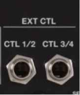
The ES-5 has two EXT CTL output jacks on the rear panel, labelled CTL1/2 and CTL3/4 These jacks connect to any external device that use ¼” jacks for control functions, (e.g. amplifier footswitch jack, delay pedal tap tempo input, modulation pedal expression input etc.) 
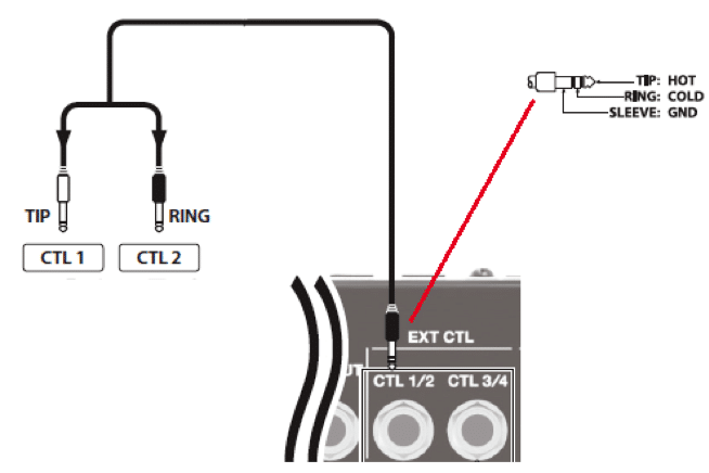
Each jack can control up to two different devices with the use of a Y-Cable. By plugging the single TRS (stereo) end of the Y-Cable into the CTL 1/2 jack, the two TS (mono) ends can then be used to control 2 different devices as shown.
NOTE: Using a TS cable (i.e. regular “mono” guitar cable), activates only the TIP send, allowing access to only ONE external control per CTL JACK.) You can view the status of the CTL 1/2 and CTL 3/4 jacks on the ES-5 by pressing EXIT repeatedly until you reach the CTL OUT screen.
The ES-5 can output a variety of control signals from these CTL jacks, including momentary, latching and pulse control signals. These control signals generate from within the ES-5 (see sections 4-2, 4-3, 4-7) or by connecting an external control pedal to the CTL IN jack (see section 4-5). Note that all settings in the CTL/EXP menu save as a part of the current patch.
ii) Using MIDI The ES-5 is a fully fledged MIDI controller and can be used to control any external device with a MIDI IN port, including digital effects pedals, rackmount processors, MIDI-Capable guitar amps, sequencers and even lighting controllers!
The ES-5 can output MIDI Program Change (PC), Continuous Control (CC) or MIDI Clock Sync messages. Each ES-5 patch can transmit up to 8 different MIDI messages simultaneously. The ES-5 also has a MIDI IN port, allowing control from other MIDI devices such as sequencers or master clock devices. To learn more about implementing MIDI control, see section 4-8 For the rest of this document, we’re going to take a look at how to implement some of the more commonly used control options, to get you started down the road of discovering the ES-5’s full capability.

4-2 ES-5 Control: Switching Channels on Your Amplifier

One of the most basic (yet useful) control functions of the ES-5 is the ability to switch channels on your guitar amplifier and save that channel setting as part of your ES-5 patch. That is to say, the ES-5 can switch your amp channel, whilst switching multiple pedals on/off simultaneously, all with one footswitch press.

The ES-5 can do this for any amplifier that uses a standard ¼” jack for footswitch control

NOTE: It is possible for the ES-5 to switch channels on some amplifiers with multi-pin DIN footswitch connectors, but to do so will require the manufacture of a custom cable, which, if assembled incorrectly, could potentially damage the ES-5 and/or your amplifier. Please consult the amplifier manufacturer to determine suitability of the amplifier controlled by an external switcher such as the ES-5.

Let’s look at how we can connect the ES-5 to a guitar amplifier’s footswitch jack and use the ES-5 to change channels.

Example:

The EXT CTL jacks will initially default to outputting a latching style footswitch signal – the most common style of footswitch jack operation. Some amplifiers however merely require a momentary pulse signal in order for their channel switch to occur.

The ES-5 can send a momentary pulse signal, rather than a latching signal, within the PLAY OPTION menu as follows:

Example:

        1. Press EDIT
        2. Use the [◄ ] [► ] buttons to scroll to the Play Option Menu and press ENTER
        3. Scroll to the Controller page and press ENTER
          ES-5_17
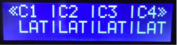
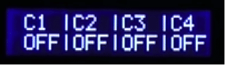
          Note that all CTLs have defaulted to “LAT” (Latching)
      1. Move the cursor to C1 then use the [ -] [ + ] buttons to toggle the display to read “PLS” (Pulse). CTL1 will now output a momentary PULSE control signal when activated
      2. If this does not work, it may mean that your amplifier requires a pulse of inverted polarity. If this is the case, then set C1 status to “INV”
      3. Exit to the Play Screen by pressing EXIT > EXIT. The Play Options save automatically

The ability of the ES-5 to output various types of signal from its EXT CTL jacks makes it extremely useful to interface with a variety of devices and functions that have a ¼” control jack.

Another of the most useful features is the ability for the ES-5 to set the TAP TEMPO of any external delay pedal with a tap tempo input jack.

4-3 ES-5 Control: Automatically send TAP TEMPO Control

It is a very common feature of modern delay pedals to be able to set their delay time by way of an external TAP TEMPO footswitch.

The ES-5 has the power to alleviate you of manually tapping the tempo into a pedal, by sending a precise, tempo-controlled series of taps through the EXT CTL jack when you select a patch.

Let’s see how to set up the ES-5 to automatically generate Tap Tempo signals from an EXT CTL jack.

Example:
      1. Connect a ¼” jack cable between the CTL 1/2 jack and the Tap Tempo input of your delay pedal
      2. Press EDIT
      3. Use the [◄ ] [► ] buttons to scroll to the Play Option Menu and press ENTER
      4. Scroll to the Controller page (see below) and press ENTER
        ES-5_18
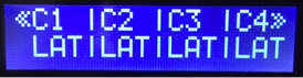
      5. Move the cursor to C1 then use the [ – ] [ + ] buttons to toggle the display to read “TP2”, “TP3” or “TP4”. This dictates whether the ES-5 will send 2, 3 or 4 tap pulses when activated.
        This setting depends on your delay pedal. i.e. if your delay pedal requires three taps to set the tempo, then you should set the C1 parameter to “TP3
      6. Press EXIT until you reach the Patch Name Screen or Patch Number Screen. Note that the bottom right hand side of the display shows the current tempo setting in BPM.
        ES-5_19
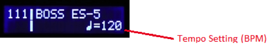
      7. Use the [ – ] [ + ] buttons to set the desired tempo
      8. Press the EXIT button repeatedly until you get to the CTL Out Screen
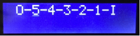
      9. Scroll to C1 and use the [ – ] [ + ] buttons to determine the note value (relative to the Tempo setting) that you wish the tap tempo to automatically tap.
        ES-5_20
        i.e. Selecting ♩ (Quarter note) will send tap pulses at the tempo selected (i.e. 120bpm)
        Selecting ♪ (Eighth note) will send tap pulses at twice the speed of the tempo selected
        In this case, we have selected a dotted eight note.
      10. Save this setting by pressing WRITE > ENTER > ENTER

NOTE: You can set different tap tempo times for every patch on the ES-5.

While automated functionality is available within the ES-5, manual control of various functions is also available.

Built with portability in mind, the ES-5 has a limited number of footswitches on its chassis. However, it does have the capability to add external control / expression pedals that are assignable to perform a diverse variety of functions.

4-4: ES-5 Control: Adding Control or Expression Pedals

ES-5_21
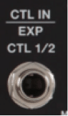
On the rear panel of the ES-5 is a jack that enables you to connect up to 2 external Control Pedals or a single Expression Pedal.
Expression Pedal
Connecting an expression pedal allows you to do two things:
  1. Control the Master Tempo using the expression pedal
  2. Transmit MIDI Continuous Control messages to compatible devices via the MIDI OUT port. This allows you to use the Expression Pedal to deliver a full range of control to any supported parameter of your MIDI capable device and is a very powerful expansion tool.
    (For more information on MIDI Expression Pedal usage see section 4-7)

*NOTE: Expression Pedals assign to the EXT CTL output jacks, but they will only output ON and OFF signals, depending on the position of the pedal. The ES-5 does not support analog output of the full range of Expression Pedal values via the EXT CTL jacks.

Control Pedals
The CTL IN jack also integrates up to 2 external control pedals – depending on the pedal and connecting cable used. See the chart below for four examples of external CTL pedal configurations.

Please note that all pedals should be set for momentary (unlatching) operation. If latching style operation is required, you can configure it within the ES-5.

Once you have connected an external control pedal, it can perform a myriad of functions, which we will look at a little later (see section 4-6). For now though, let’s look at how to configure an external footswitch as a manual TAP TEMPO to change the delay time on a DD-7 delay pedal.

Example:

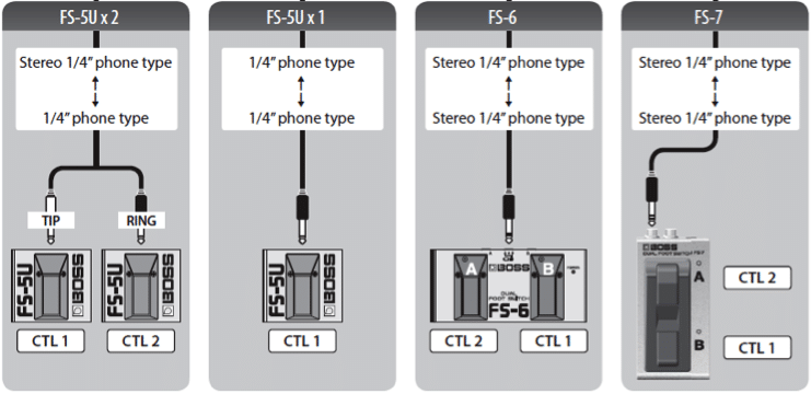
1) Connect an external momentary-style footswitch to the CTL IN jack using a ¼” jack cable.
*Note: In the video, a mono (TS) cable is used. This means that only CTL 1 is active and ready for use. CTL 2 will not be accessible.

2) Connect a ¼” jack cable between the ES-5’s EXT CTL 1/2 jack and the DD-7’s TEMPO jack.

3) Press EDIT. Scroll to the CTL/EXP menu and press ENTER

4) Scroll to CTL IN 1 menu and press ENTER. You’ll see this screen:
ES-5_23

Func: What target function the CNTL IN 1 is going to assign to control. In this case, it assigned to send a signal out of Ctl1. (i.e. EXT CTL 1)

Min/Max: This specifies the signal sent when pressing the switch (Max) and when it is released (Min). Leave these settings as they are.

Mod: What mode of operation we would like the Control Pedal to operate.
The two available options are MOM or TGL: Momentary or Toggle (Latching).
For a Tap Tempo, Momentary is correct, so we do not need to change anything.

5) Ensure the Delay pedal loop has activated and play guitar. Note the delay tempo.

6) Use the external footswitch to tap in a different tempo. Play guitar and note that the delay tempo has now changed.

Hopefully, you can see from the example above, that using external controls is a very useful tool with dozens of different applications achievable (depending on your connected gear.)

In actual fact, the ES-5 has the capability to not only use external pedals to perform advanced tasks, but its own footswitches can be reconfigured and repurposed to perform almost any task you can think of. Let’s look deeper into the CTL/EXP menu to understand how much flexibility is there.

4-5: ES-5 Control: Reassigning the ES-5’s footswitches

For those who find the ES-5 footswitch layout not to their liking, or have some buttons that are surplus to requirement, the ES-5 offers the ability to reassign the footswitches to a variety of different tasks.

Example:
To reassign the function of any footswitch on the ES-5:
  1. Press EDIT
  2. Scroll to the CTL/EXP menu and press ENTER
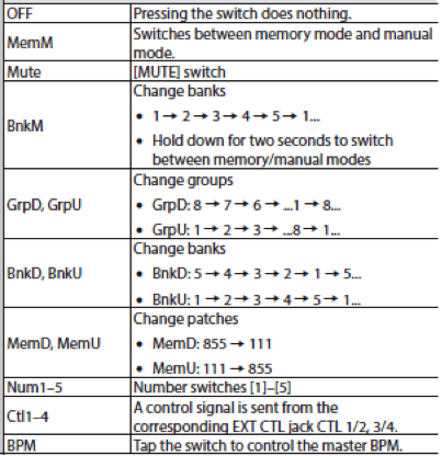
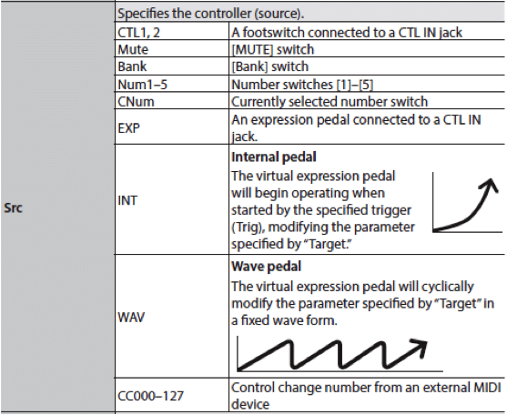
  3. Scroll through to which of the footswitches you wish to reassign (BANK, MUTE or one of the numbered footswitches (1-5)) and press ENTER
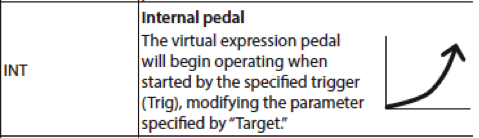
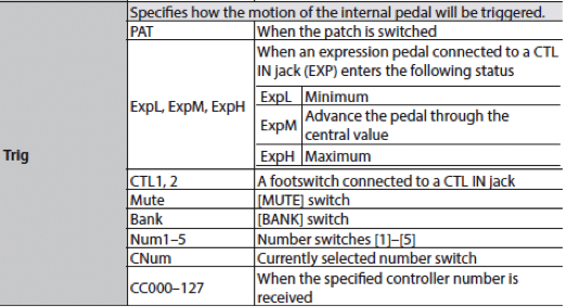
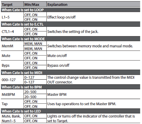
  4. You can now select from a variety of functions that the selected footswitch will now perform INSTEAD of its original function (see chart below).ES-5_24
  5. If you elect to use the footswitch to send a signal out of the EXT CTL 1/2 or CTL 3/4 jack, there are some additional options available.ES-5_25
  6. Save the setting by pressing WRITE > ENTER > ENTER

Changing the operation of a footswitch is merely scratching the surface of the powerful assign capabilities of the ES-5. Once you understand the full CTL Assign capability of the ES-5, you begin to open the door to endless possibilities.

Let’s take a closer look:

4-6: ES-5 Control: Understanding and Using CTL Assigns

A lot of the ES-5’s exceptional power lies within the Assigns, located within the CTL/EXP menu. The advanced user should become very familiar with how to use these assigns to perform a variety of tasks.

To understand the Assigns, it is important to understand the concept that, to assign a control, you much specify a source and a target – which requires an understanding of these two terms’ meaning:

Source: What method generates the control signal
Target: What parameter(s) do we wish to control using the source signal.

Example:
Let’s look at an advanced control function and how to program it:

SITUATION: We have a Phaser pedal connected to Loop 4 of the ES-5.

On a particular patch (which usually has Loop 4/Phaser switched OFF), we wish to be able to switch the Phaser ON by momentarily holding down the illuminated footswitch of the currently selected patch.

1. Press EDIT. Scroll to the CTL/EXP menu and press ENTER

2. Scroll through to the Assign 1 menu and press ENTER. You’ll see this screen:

Sw = Switch the Assign ON or OFF
Src = Defines the Assign Source*
Mod = Select the operating mode of the source. Momentary or Toggle.

3. Turn the Assign Switch (Sw) ON.

4. Select the Source. Here is a list of all available Assign Sources:

In this case, we wish to select CNum. This very useful assign source allows you to assign functionality to the illuminated footswitch of whichever patch number currently selected.

5. Set the mode to MOM (Momentary). We wish the Phaser to operate only while the footswitch is depressed.

6. Scroll the cursor to the right to the next page, which is where we define the Target Category (Cate), and Target that the source will act upon.
Here is the complete list of targets/categories:

Our goal is to have the source footswitch momentarily turning on the Phaser in Loop 4, so we will set the Cate (category) to LOOP and the Target to L4.

7. Save the setting by pressing WRITE > ENTER > ENTER

8. Exit to the Play Screen

9. Play guitar and note the clean signal.

10. Hold down the illuminated footswitch (i.e. the footswitch corresponding to your current patch) and note that the Phaser is applied whilst your foot is held down.

Congratulations! You now understand how to perform advanced assign functions by being able to select a Source and assign it to a Target.

Every patch on the ES-5 allows up to eight independent CTL Assigns which, as you can imagine, opens up a huge amount of control power particularly once you add MIDI into the mix. Whilst MIDI commands can be assigned using the above CTL Assigns, you can also assign a further 8 static MIDI controls within the Patch settings for even more control options.

Let’s take a closer look into the ES-5’s MIDI control capability.


4-7 ES-5 Control: MIDI Control

Although some guitarists approach the concept of MIDI control with extreme trepidation, there is, in reality, little reason to be afraid of it. The basic concepts are not too difficult to grasp and once understood – provide a guitarist with the ultimate means to be able to control many types of musical equipment devices in perfect synchronisation and with ultimate flexibility.

The ES-5 is capable of performing both Program Changes and Control Change (Continuous Control) output functions via MIDI.

i) MIDI Program Changes
This is the most common type of MIDI control used by guitar players. By using the ES-5 to broadcast a MIDI program change message to another MIDI-compatible device, (for example a Boss DD-500 Digital Delay), it means that when you press a footswitch button to select a patch on the ES-5, it can simultaneously change the patch of the DD-500.

You can apply a different DD-500 patch to every ES-5 patch, without ever needing to touch the DD-500 during performance.

Let’s look at how to setup the ES-5 to perform program changes via MIDI. We’ll use a DD-500 pedal connected into Loop 1.

Example:
  1. Start on patch 111 of the ES-5. (Footswitch #1)
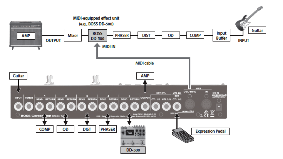
  2. Connect a MIDI cable from the ES-5’s MIDI OUT port to the DD-500’s MIDI IN port. Note: This configuration means that the ES-5 will be the controller for the DD-500. Not vice versa.
  3. Press EXIT repeatedly until you get to the Loop on/off screen. Turn Loop1 ON.
  4. Press EDIT, scroll to the PATCH menu and press ENTER
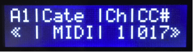
  5. Scroll to Patch MIDI 1 and press ENTER. You’ll then see this screen:
    ES-5_30Ch: Selects the MIDI Channel (#1-16) that the ES-5 will broadcast the message. (most devices default to channel 1)LSB/MSB: Stands for Least Significant Byte and Most Significant Byte. These relate to more advanced MIDI usage, unnecessary for this document. They allow you to change banks/patches on units with more than 128 presets. In this example, leave them set to OFF.PC: Program Change. This selects the program change number that broadcasts from the ES-5 – thereby telling the DD-500 which patch to select.
    Note: All MIDI devices should contain MIDI Program Change Maps within their owner’s manual/documentation. A Program Change Map will show which MIDI Program Change number corresponds to each patch preset number on the target device.
  6. Set Ch (MIDI channel) to 1
    Set PC (Program Change) to 1.
    This says to the ES-5: “I want to use MIDI channel 1 to tell the DD-500 to change to preset 1
  7. WRITE the changes to this patch and name it “BOSS ES-5 A
  8. Exit to the Play Screen then press footswitch 2 to go to a new patch on the ES-5
  9. Repeat steps 3-5
  10. Set Ch (MIDI channel) to 1
    Set PC (Program Change) to 2.
    This says to the ES-5: “I want to use MIDI channel 1 to tell the DD-500 to change to preset 2
  11. WRITE the changes to this patch and name it ”BOSS ES-5 B
  12. EXIT to the play screen
  13. Press footswitch 1 to go back to the first patch. Note that the DD-500 is on preset number 01A.
  14. Press footswitch 2. Note that the DD-500 simultaneously changes to preset 2.

MIDI Program changes are very powerful. Because MIDI devices can be daisy-chained (using MIDI THRU ports), plus adding in the factor that the ES-5 can send up to 16 unique MIDI messages simultaneously, you can simultaneously change patches on as many devices as you could ever feasibly string together – all with a single footswitch tap.

Program changes are not the only type of MIDI message though. We can also use MIDI to change parameters of MIDI compatible devices in real time, using MIDI Control Change (sometimes called Continuous Controller) messages.

ii) MIDI Control Change (Continuous Controller)
As a fully-fledged MIDI controller, the ES-5 can broadcast MIDI CC signals allowing you to perform realtime changes of various parameters of MIDI Compatible devices (For a list of what parameters are controllable, you should refer to the owner’s manual of the target device.) These signals can either be generated from with the ES-5 itself, or by using Expression or Control pedals connected to the ES-5’s CTL IN jack Let’s look at an example where we wish to connect an Expression pedal to the ES-5 and then use that to alter the FEEDBACK rate of the DD-500 in real time via MIDI.

1) Connect an Expression pedal to the CTL IN jack of the ES-5.

2) Connect a MIDI cable from the ES-5 MIDI OUT into the DD-500 MIDI IN

3) On the ES-5, press EDIT, scroll to the CTL/EXP menu and press ENTER

4) Scroll to Assign 1 and press ENTER.

5) Set Switch (Sw) to ON. Set Source (Src) to EXP (Expression Pedal)
a. Keep Scrolling to the right. Change the Category (Cate) to MIDI. You’ll see this screen:

Ch = MIDI transmit channel. This should be set the same as the MIDI Receive (Rx) channel on the DD-500. This usually defaults to channel 1 on both devices.

CC# = Control Change Number. Refer to the documentation of the target device to determine which CC# we should select. See below for a sample from the DD-500 manual, showing which functions are controllable by MIDI CC messages and which CC# to use:

Excerpt from Boss DD-500 manual (p.20)

Note that the FEEDBACK control assigns to MIDI Control number 17. Therefore, on the ES-5 we should set CC# to 017

6) Keep Scrolling to the right to check the Range settings on the next 2 pages:

Min / Max Sets the available range of values that the Expression pedal is able to send, from the Min position (Heel down) to the Max position (Toe down).
This should normally be set Min = 0, Max = 127 for normal operation.

Act L / Act H Sets the active range of the expression pedal, within the Min/Max range specified earlier.

This should normally be set Min = 0, Max = 127 for normal operation.

7) Save these settings by pressing WRITE > ENTER > ENTER

8) Play guitar (with the DD-500 activated) and note that operating the Expression pedal will now control the FEEDBACK parameter of the DD-500.

The ES-5 contains another control function, unique to the BOSS ES-series effects, that offers an alternative way to provide MIDI Continuous Control, without having to have a physical Expression pedal connected. It’s called the internal Virtual Expression Pedal.

4-8 ES-5 Control: Using the Virtual Expression pedal

The Virtual Expression Pedal contained within the ES-5 offers the opportunity for the user to perform a variety of functions that are traditionally handled by a manual Expression pedal, but without the need to have one taking up space on your pedalboard or the hassle of having to operate it.

This Virtual Expression pedal is available as one of the CTL/EXP Assign Sources and assigns to modify any of the usual target parameters.

*NOTE: Expression Pedals assign to the EXT CTL output jacks, but they will only output ON and OFF signals, depending on the position of the pedal. The ES-5 does not support analog output of the full range of Expression Pedal values via the EXT CTL jacks.

Virtual Expression Pedals will deliver their full range of values when used as a source for MIDI Continuous Control.

The Virtual Expression Pedal is available to use in two standard modes of operation, both highly customisable: INT and WAV.

i) INT mode

As with any assigned control function (refer section 4-6) the Internal Expression pedal is a Source that acts upon a target.

The difference though, is that it is not an instantaneous control. Just like using an actual expression pedal, the virtual pedal outputs a dynamic set of parameters over a period of time. The INT mode will cause the ES-5 to send a control signal that is equivalent to operating one movement of an expression pedal, from heel down (min) to toe down (max).

One possible use for this function might be to perform a gradual volume increase when you select a particular patch. By assigning the INT Virtual Expression pedal as a source to control the output level of a MIDI controllable target device, you could program it to start at a low volume and then bring the volume up over a few seconds.

To enable proper operation of this time-based function, we introduce some new parameters into the equation – Trigger, Time and Curve.

Trigger: Chooses what event will trigger the internal expression pedal to begin its operation:

Time: Selects the time that it will take for the virtual expression pedal to move from MINIMUM VALUE to MAXIMUM value. The selectable range is from an arbitrary 0-100 scale.

Curve: Selects one of three curves that affect the rate of value change throughout the virtual pedal’s motion. The available curves are Linear, Slow and Fast

ii) WAV mode

This mode is similar to the effect of constantly cycling an Expression Pedal from heel to toe and back again in a constant fashion.

This could be useful if, for example, you used it to control (via MIDI) the resonant frequency of a filter effect. The ES-5’s WAV mode could cycle that frequency up and down, effectively becoming an auto-wah effect.

Unlike the INT mode, there is no Trigger parameter. When the WAV mode assigns to a particular patch, it will begin cycling as soon as that patch is selected.

There are however two adjustable parameters for setting the cycle Rate as well as the shape of the cyclic waveform.

ES-5 Summary

As you have seen throughout this guide, the ES-5 is a phenomenally powerful tool for controlling your guitar rig. From its most basic functionality as a pedal loop switcher, all the way through to its advanced MIDI and Expression capabilities, the ES-5 packs more power into its compact chassis than is almost imaginable.

We’ve shown how the ES-5 can perform a plethora of control functions and how, with the single tap of a footswitch, you can use its 16 control assigns (8x MIDI, 8 x General) to operate every feasible aspect of your pedals, amplifier and other external devices in complete synchronicity.

By studying this guide, and the ES-5 product manual, you can become a master of the ES-5; you will bring a new level of flexibility and power to your guitar rig, leaving you to be able to devote more attention to that most important part of the tone chain…..your playing!

Related Products

Related Posts

Scroll to Top

SIGN UP TO DOWNLOAD
THIS TD-50 CUSTOM PATCHES

Created by Roland V-Drums specialist Simon Ayton, these patches were designed using the internal factory sounds and many of the techniques covered in the TD-50 guide. Enjoy exploring the possibilities!